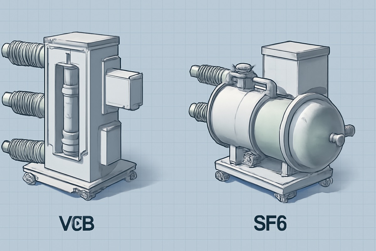
What Is a Vacuum Interrupter (Vacuum Bottle)?
A vacuum interrupter — also called a vacuum bottle interrupter in North American industry terminology — is the core arc-extinguishing component inside every vacuum circuit breaker and vacuum contactor. It is a hermetically sealed ceramic-and-metal assembly containing two electrical contacts in a high-vacuum environment (approximately 10-4 Pa, or one ten-millionth of atmospheric pressure).
When the contacts separate during a switching or fault-clearing operation, the electrical arc that forms is extinguished by the vacuum itself — the fastest and cleanest arc-extinguishing method available in medium-voltage power systems. Because the vacuum interrupter is sealed for life, it requires no gas refilling, no oil maintenance, and no arc-chute replacement over its entire 20-30 year service life.
This guide focuses on what engineers and procurement teams most need to know: the three main types of vacuum interrupters (plain break, AMF, and RMF), how to match the right type to your switchgear application, and the critical specifications that determine performance and reliability at 12 kV, 24 kV, and 40.5 kV voltage classes.
How a Vacuum Interrupter Works: Arc Quenching in Vacuum
Understanding the arc-extinguishing physics is essential for selecting the correct vacuum interrupter type. The process follows a precise sequence:
- Contact separation: The operating mechanism (spring or magnetic actuator) drives the moving contact away from the fixed contact. The contact gap opens to 8-12 mm for 12 kV class, 12-16 mm for 24 kV, or 16-20 mm for 40.5 kV.
- Metal-vapor arc formation: At the instant of separation, a metal-vapor arc forms in the vacuum gap. Unlike arcs in air or SF6, this arc consists entirely of metal vapor evaporated from the Cu-Cr contact surfaces — there are no gas molecules to ionize.
- Arc control: The contact geometry generates a magnetic field (axial or radial, depending on interrupter type) that controls the arc behavior — either keeping it diffuse across the full contact face (AMF) or driving it to rotate around the contact periphery (RMF).
- Current zero extinction: At the first natural current zero crossing (every 10 ms at 50 Hz, every 8.3 ms at 60 Hz), the arc extinguishes. The metal vapor condenses on the arc shield and contact surfaces within microseconds.
- Dielectric recovery: The vacuum gap recovers its full dielectric strength at a rate of 10-20 kV/microsecond — 10 to 100 times faster than SF6 or oil. This extremely fast recovery prevents arc re-strike even under severe transient recovery voltage (TRV) conditions.
The total interruption time from contact separation to arc extinction is typically 8-15 milliseconds. This rapid, clean arc-extinguishing process is why vacuum interrupters dominate medium-voltage switching worldwide — an estimated 80% of all new MV circuit breakers installed globally use vacuum technology.
Contact Materials: Why Cu-Cr Alloy Is the Industry Standard
The contact material is the single most critical factor determining a vacuum interrupter's breaking performance, electrical life, and switching characteristics. The industry standard is copper-chromium (Cu-Cr) alloy, typically in a 75% Cu / 25% Cr composition, manufactured by powder metallurgy or vacuum arc melting.
Cu-Cr delivers the optimal balance across five competing requirements:
- High electrical conductivity (from copper) — minimizes contact resistance and I2R heating during continuous current flow. Typical contact resistance: 15-50 micro-ohms.
- Anti-welding resistance (from chromium) — prevents the contacts from fusing together under high fault currents. Critical for reliable opening after a short-circuit event.
- Low chopping current — Cu-Cr typically produces 3-5 A chopping current, acceptable for most distribution applications. Lower than WCu (5-8 A) and safe for transformer and motor switching.
- Arc erosion resistance — chromium particles provide stable arc behavior and resist excessive material loss. A Cu-Cr contact can withstand 20-100 full short-circuit interruptions at rated breaking capacity.
- Fast dielectric recovery — the vacuum gap between Cu-Cr contacts recovers dielectric strength rapidly after arc extinction, enabling reliable interruption at the first current zero.
For specialized applications, alternative contact materials are available:
| Contact Material | Composition | Chopping Current | Breaking Capacity | Best Application |
|---|---|---|---|---|
| Cu-Cr (standard) | 75% Cu, 25% Cr | 3-5 A | Up to 63 kA | General distribution, transformer switching, motor control |
| Cu-Bi | Cu + 0.5% Bi | 1-2 A | Up to 25 kA | Capacitor bank switching (minimal transients) |
| W-Cu | W with Cu infiltration | 5-8 A | Up to 80 kA | Generator breakers, very high current ratings |
| Ag-WC | Ag-WC composite | 0.5-1 A | Up to 16 kA | Contactors, ultra-sensitive load switching |
NAIJI Electric's vacuum circuit breakers use powder-metallurgy Cu-Cr contacts processed under controlled atmosphere to ensure uniform chromium distribution and consistent arc behavior. For details on manufacturing technology, see our Cu-Cr contact materials guide.
Vacuum Interrupter Types: Plain Break vs AMF vs RMF
The three main vacuum interrupter designs differ in how they control the arc between the contacts during fault-current interruption. The arc-control method determines the maximum breaking capacity, contact erosion pattern, and suitability for different voltage classes.
1. Plain Break (Butt Contact) Vacuum Interrupter
The simplest design — flat-faced contacts with no special arc-control geometry. The arc burns in a constricted column between the contacts. Suitable only for low-current applications where the arc energy is small enough to be absorbed without magnetic field control.
- Breaking capacity: Up to 8-10 kA
- Typical voltage: 7.2-12 kV
- Mechanical life: 10,000-20,000 operations
- Contact gap: 6-8 mm
- Application: Vacuum contactors, load switches, low-duty circuit breakers
- Advantage: Simple, low cost, compact
- Limitation: Concentrated arc causes severe local contact erosion at high currents
2. Radial Magnetic Field (RMF) Vacuum Interrupter
Uses spiral-slotted contacts to generate a tangential magnetic field perpendicular to the arc column. This field drives the arc to rotate rapidly around the contact periphery at speeds of 50-200 m/s, distributing arc energy across the full contact circumference and preventing localized overheating.
- Breaking capacity: Up to 25-31.5 kA
- Typical voltage: 12-24 kV
- Mechanical life: 10,000-30,000 operations
- Contact gap: 8-12 mm (12 kV), 12-16 mm (24 kV)
- Application: Standard distribution VCBs, indoor switchgear panels, ring main units
- Advantage: Good balance of performance and cost, proven reliability
- Limitation: Arc rotation may become unstable at very high currents (>31.5 kA)
3. Axial Magnetic Field (AMF) Vacuum Interrupter
Uses cup-shaped contacts or external coils to generate a magnetic field parallel (axial) to the arc column. This keeps the arc in a diffuse mode spread uniformly across the entire contact surface area, rather than concentrating at the edges. Diffuse-mode arcing produces the lowest contact erosion per interruption and enables the highest breaking capacities.
- Breaking capacity: Up to 40-63 kA
- Typical voltage: 12-40.5 kV
- Mechanical life: 20,000-30,000 operations
- Contact gap: 10-12 mm (12 kV), 16-20 mm (40.5 kV)
- Application: High-fault-level substations, generator breakers, metal-clad switchgear, 40.5 kV systems
- Advantage: Highest breaking capacity, lowest contact erosion, longest electrical life
- Limitation: More complex manufacturing, higher cost
Head-to-Head Comparison Table
| Parameter | Plain Break | RMF (Radial Magnetic Field) | AMF (Axial Magnetic Field) |
|---|---|---|---|
| Arc Control Method | None (constricted arc) | Rotating arc (tangential field) | Diffuse arc (axial field) |
| Contact Design | Flat butt contacts | Spiral-slotted contacts | Cup-shaped or coil contacts |
| Max Breaking Capacity | 8-10 kA | 25-31.5 kA | 40-63 kA |
| Voltage Range | 7.2-12 kV | 12-24 kV | 12-40.5 kV |
| Contact Erosion Rate | High (concentrated) | Medium (distributed around edges) | Low (uniform across surface) |
| Electrical Life (fault ops) | 10-20 operations | 20-50 operations | 50-100 operations |
| Mechanical Life | 10,000-20,000 ops | 10,000-30,000 ops | 20,000-30,000 ops |
| Manufacturing Complexity | Low | Medium | High |
| Relative Cost | 1.0x (baseline) | 1.3-1.5x | 1.8-2.5x |
| Typical Application | Contactors, load switches | Distribution VCBs, RMUs | Substation VCBs, generator breakers |
Vacuum Interrupter Ratings by Voltage Class
Vacuum interrupters are manufactured for specific voltage classes, each with distinct contact gap distances, BIL (basic insulation level) requirements, and breaking capacity ranges. The following table summarizes the key specifications per IEC 62271-100:
| Voltage Class | System Voltage | Contact Gap | BIL (Lightning Impulse) | Max Breaking Capacity | Common Application |
|---|---|---|---|---|---|
| 7.2 kV | 6 kV / 6.6 kV | 6-8 mm | 60 kV | 25 kA | Industrial MCC, mining |
| 12 kV | 10 kV / 11 kV | 8-12 mm | 75 kV | 50 kA | Distribution, switchgear, RMUs |
| 24 kV | 20 kV / 22 kV | 12-16 mm | 125 kV | 40 kA | Urban distribution, wind farms |
| 40.5 kV | 33 kV / 35 kV | 16-20 mm | 185 kV | 40 kA | Substations, industrial plants, solar farms |
As the voltage class increases, the contact gap must widen to maintain adequate dielectric withstand. This is why 40.5 kV vacuum interrupters are physically larger than 12 kV units — the longer contact travel also requires a more robust bellows assembly, which partly explains the higher cost of HV vacuum interrupters.
Selection Guide: How to Choose the Right Vacuum Interrupter
Selecting the correct vacuum interrupter for your MV switchgear involves matching six critical parameters to your system requirements:
Step 1: Determine Voltage Class
Match the interrupter's rated voltage to your system voltage with the standard step-up factor: 12 kV rated for 10/11 kV systems, 24 kV for 20/22 kV, 40.5 kV for 33/35 kV. Never install an interrupter rated below your maximum system voltage.
Step 2: Verify Breaking Capacity
The interrupter's rated short-circuit breaking current (in kA) must exceed the prospective fault current at the installation point. For 12 kV distribution networks, typical fault levels range from 16-25 kA; for substation bus sections, 31.5-50 kA. Choose the interrupter type accordingly:
- ≤10 kA: Plain break (contactors, load switches)
- 16-31.5 kA: RMF type (standard distribution VCBs)
- 31.5-63 kA: AMF type (substation and industrial VCBs)
Step 3: Match Rated Current
The interrupter's rated continuous current must exceed your maximum load current with margin. Standard ratings: 630 A, 1250 A, 2000 A, 2500 A, 3150 A, 4000 A, 5000 A. Higher current ratings require larger contact diameters and heavier copper conductors.
Step 4: Assess Mechanical Life Requirements
Estimate the expected number of operations over the asset life. Low-duty applications (utility feeder protection, 50-100 operations/year) can use standard 10,000-operation interrupters. High-duty applications need higher ratings:
- Capacitor bank switching: 3-6 operations/day × 365 days = 1,000-2,000 operations/year → need 30,000+ mechanical life
- Motor starting (frequent): 10-50 starts/day → need 20,000-50,000 mechanical life (consider vacuum contactor instead)
- Automatic recloser duty: 2-3 shots per event, multiple events/year → need 10,000-20,000 mechanical life
Step 5: Choose Contact Material
Cu-Cr is the correct choice for 90% of applications. Specify Cu-Bi only for dedicated capacitor switching (minimizes voltage transients). Specify W-Cu only for generator breakers or applications exceeding 50 kA.
Step 6: Verify Dimensional Compatibility
The replacement interrupter must physically fit inside the circuit breaker or switchgear. Critical dimensions: overall length, flange diameter, bolt circle, total stroke, and contact gap at full open position. NAIJI Electric provides dimensional cross-reference data for all common industry models.
Application Matching: Which Type for Which Switchgear?
| Application | Typical Fault Level | Recommended VI Type | NAIJI Electric Model |
|---|---|---|---|
| Outdoor distribution line (pole-mounted VCB) | 12.5-20 kA | RMF, 12 kV | ZW32-12 (20 kA) |
| Indoor switchgear panel (distribution) | 20-31.5 kA | RMF, 12 kV | VS1-12 (31.5 kA) |
| Ring main unit (RMU) | 16-25 kA | RMF, 12-24 kV | RMU series |
| Substation bus-coupler / bus-section | 31.5-50 kA | AMF, 12 kV | VN3-12E (50 kA) |
| Industrial plant main breaker | 25-40 kA | AMF, 12-24 kV | CE-12 (50 kA, 50,000 ops) |
| 35 kV substation / transmission | 25-40 kA | AMF, 40.5 kV | VN1-40.5E (40 kA) |
Vacuum Interrupter Lifespan & Replacement Criteria
A vacuum interrupter reaches end of life when any one of these three criteria is met — whichever comes first:
- Mechanical life exhausted: The bellows has cycled through its rated number of operations (10,000-30,000). Beyond this point, bellows fatigue cracks may develop and compromise the vacuum seal.
- Electrical life exhausted: The contacts have performed the rated number of short-circuit interruptions (20-100 at rated breaking capacity). Contact erosion reduces the effective gap and dielectric withstand capability.
- Vacuum integrity lost: A micro-crack, braze joint failure, or bellows perforation allows air to leak into the interrupter. Detected by hi-pot test (leakage >1 μA at rated test voltage). A vacuum interrupter with lost vacuum cannot be repaired — it must be replaced.
In practice, most vacuum interrupters in standard distribution service last 20-30 years without reaching any of these limits. The most common reason for replacement is vacuum loss detected during scheduled maintenance testing, not wear-out. This is why regular testing on a 5-8 year cycle is essential — a failed interrupter shows no visible external signs.
Common Selection Mistakes to Avoid
- Under-rating breaking capacity: Selecting a 20 kA interrupter for a 25 kA fault-level installation. Always include a safety margin — select the next standard rating above the prospective fault current.
- Ignoring switching duty: Specifying a 10,000-operation interrupter for a capacitor-switching application that performs 2,000 operations per year. The interrupter would reach mechanical end-of-life in 5 years instead of the expected 25.
- Wrong contact material: Using standard Cu-Cr for dedicated capacitor bank switching. Cu-Cr's 3-5 A chopping current can produce voltage transients that damage capacitors — use Cu-Bi (1-2 A chopping) instead.
- Dimensional mismatch: Replacing a vacuum interrupter with a different brand or model without verifying stroke, gap, and flange dimensions. Even 1-2 mm differences in contact gap can compromise breaking performance and violate IEC 62271-100 type-test certification.
- Neglecting altitude derating: At altitudes above 1,000 m, reduced air density decreases external insulation strength. The vacuum interrupter's internal performance is unaffected (it operates in vacuum), but the external creepage and clearance distances of the breaker must be increased.
NAIJI Electric Vacuum Interrupter Technology
All NAIJI Electric vacuum circuit breakers use high-performance vacuum interrupters with powder-metallurgy Cu-Cr contacts, manufactured and tested to IEC 62271-100 and GB 1984 standards. Our product range covers every vacuum interrupter type and voltage class:
- ZW32-12 — 12 kV / 630 A / 20 kA, RMF interrupter, 10,000 operations. Outdoor pole-mounted distribution VCB.
- VS1-12 — 12 kV / 2500 A / 31.5 kA, RMF interrupter, 20,000 operations. Standard indoor switchgear VCB.
- VN3-12E — 12 kV / 5000 A / 50 kA, AMF interrupter, 30,000 operations. High-fault-level substation VCB.
- CE-12 — 12 kV / 5000 A / 50 kA, AMF interrupter, 50,000 operations. Ultra-high mechanical life for frequent-switching applications.
- VN1-40.5E — 40.5 kV / 3150 A / 40 kA, AMF interrupter. 35 kV substation and industrial applications.
NAIJI Electric can also supply replacement vacuum interrupters cross-referenced to common industry models for switchgear retrofit and maintenance programs. All interrupters undergo 100% factory testing including vacuum integrity, contact resistance, and BIL withstand before shipment.
Need Help Selecting a Vacuum Interrupter?
Choosing the right vacuum interrupter type, voltage class, and breaking capacity is critical for switchgear performance and safety. NAIJI Electric's engineering team provides free technical consultation for vacuum interrupter selection, cross-referencing, and replacement programs.
Contact us with your system voltage, fault level, switching duty, and existing equipment model — we will recommend the optimal vacuum interrupter specification and provide a quotation within 24 hours.
Related guides: Vacuum Interrupter Working Principle | Cu-Cr Contact Materials Guide | VI Testing & Maintenance Checklist | VCB vs SF6 Comparison | Circuit Breaker Ratings Explained