Quick Answer: What Is Medium Voltage?
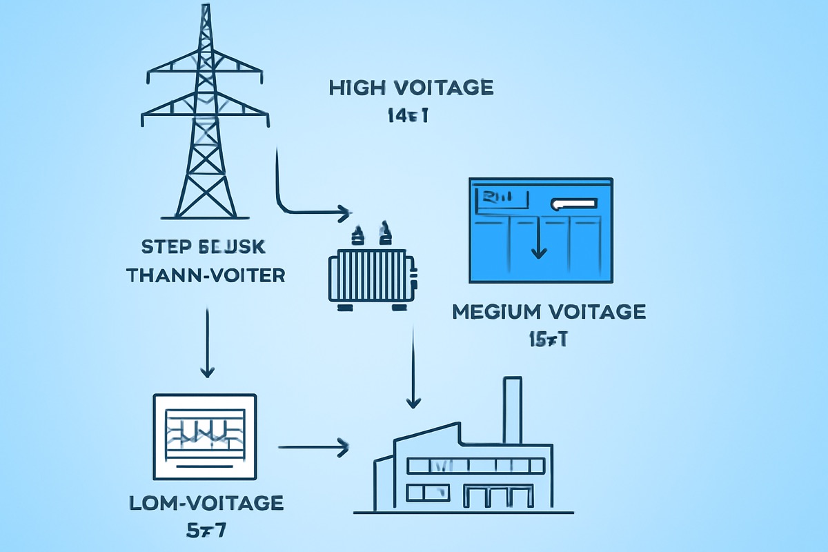
Medium voltage (MV) refers to electrical power systems operating between 1 kV and 35 kV (IEC definition) or 1 kV to 69 kV (IEEE/ANSI definition). It is the voltage class used to distribute power from substations to buildings, factories, and neighborhoods. Medium voltage sits between low voltage (below 1 kV, used inside buildings) and high voltage (above 35-69 kV, used for long-distance transmission). Most industrial and commercial facilities receive power at medium voltage and transform it down to low voltage for use by equipment.
Voltage Range Definitions by Standard
| Standard / Region | Low Voltage | Medium Voltage | High Voltage |
|---|---|---|---|
| IEC 60038 | Up to 1 kV | 1 kV - 35 kV | Above 35 kV |
| IEEE / ANSI | Up to 1 kV | 1 kV - 69 kV | Above 69 kV |
| China (GB) | Up to 1 kV | 1 kV - 40.5 kV | Above 40.5 kV |
| Europe (CENELEC) | Up to 1 kV | 1 kV - 36 kV | Above 36 kV |
| US (NEC practice) | Up to 1 kV | 2.4 kV - 69 kV | Above 69 kV |
Common Medium Voltage Levels Worldwide
| System Voltage | Equipment Rating | Regions | Typical Use |
|---|---|---|---|
| 3.3 kV | 3.6 kV | UK, India, older systems | Industrial motors, mining |
| 6.6 kV | 7.2 kV | UK, India, Japan, mining | Large motors, industrial |
| 10 kV | 12 kV | China (standard) | Urban/rural distribution |
| 11 kV | 12 kV | UK, India, Middle East, Australia | Primary distribution |
| 13.8 kV | 15 kV | North America | Distribution, industrial |
| 20 kV | 24 kV | France, Belgium, parts of Europe | Distribution |
| 22 kV | 24 kV | Thailand, parts of SE Asia | Distribution |
| 33 kV | 36 kV | UK, India, Middle East, Africa | Sub-transmission |
| 35 kV | 40.5 kV | China | Sub-transmission, large industrial |
Why Medium Voltage Matters
Medium voltage exists because of a fundamental law: power loss is proportional to the square of the current (Ploss = I²R). By increasing the voltage, the current decreases proportionally, dramatically reducing energy losses and cable costs.
Consider delivering 1 MW of power over 1 km:
| Voltage | Current | Cable Size | Power Loss |
|---|---|---|---|
| 400 V (LV) | 1,443 A | 6 x 300 mm² parallel | ~80 kW (8%) |
| 10 kV (MV) | 58 A | 1 x 25 mm² | ~3 kW (0.3%) |
The MV solution uses a fraction of the cable and wastes far less energy. This is why any facility above approximately 300-500 kW receives power at medium voltage.
Types of Medium Voltage Equipment
Circuit Breakers
MV circuit breakers are the primary protection and switching devices. For a detailed comparison, see our vacuum circuit breaker vs SF6 comparison.
- Vacuum Circuit Breakers (VCB) — dominant at 12-24 kV, with outdoor pole-mounted (ZW32) and indoor models up to 40.5 kV
- SF6 Circuit Breakers — compact gas-insulated design for space-constrained installations (see SF6-free alternatives)
- Specialized Breakers — CES for capacitor switching, CEG for generator protection
Switchgear
MV switchgear assemblies house breakers, bus bars, disconnectors, and protection relays:
- Metal-Enclosed Switchgear — ASN series, 12 kV to 40.5 kV, up to 5000 A / 50 kA
- Gas-Insulated Switchgear (GIS) — GSN series, compact and maintenance-free, including eco-friendly nitrogen option
Ring Main Units (RMU)
Ring main units are compact switchgear for underground cable distribution networks, used extensively in urban areas. The XGN15-12 RMU offers modular switch/fuse configurations for flexible network design.
Load Break Switches
SF6 load break switches sectionalize overhead distribution feeders and automate fault isolation. The FZW28-12 boundary switch integrates SF6 insulation with intelligent fault detection for smart grid applications.
Contactors
Vacuum contactors handle frequent switching at medium voltage — motor starting, capacitor bank switching, and transformer energization. Built for high-duty-cycle operations that circuit breakers are not designed for.
Medium Voltage Applications by Industry
| Industry | Typical MV Voltage | Equipment Used |
|---|---|---|
| Utility Distribution | 10-33 kV | Switchgear, RMU, reclosers, pole-mounted VCB |
| Industrial / Manufacturing | 6.6-13.8 kV | Switchgear, MCC, VCB, contactors |
| Commercial (Data Centers, Hospitals) | 11-13.8 kV | Compact switchgear, GIS |
| Mining | 6.6-33 kV | Explosion-proof switchgear, VCB |
| Oil & Gas | 6.6-13.8 kV | Hazardous area switchgear, generator breakers |
| Renewable Energy | 20-35 kV | Collector switchgear, transformer protection |
| Rail Transit | 10-35 kV | Traction substations, GIS |
| Water / Wastewater | 6.6-11 kV | Pump motor starters, VCB, contactors |
Medium Voltage Switchgear Selection Criteria
Selecting the right medium voltage switchgear for a project requires evaluating multiple technical and commercial factors. Engineers who rush this decision often end up with equipment that is either over-specified (wasting budget) or under-specified (creating safety hazards). Here is a systematic approach to medium voltage switchgear selection:
Step 1: Determine System Voltage and Fault Level
The first two parameters to establish are the rated voltage and the prospective short-circuit current at the installation point. The rated voltage determines the equipment class (12 kV, 24 kV, or 40.5 kV), and the fault level determines the minimum breaking capacity and short-time withstand rating of the switchgear.
| System Voltage | Equipment Rating | Typical Fault Level | Common Switchgear |
|---|---|---|---|
| 10-11 kV | 12 kV | 16-31.5 kA | ASN3-12, GSN3-12, XGN15-12 |
| 20-22 kV | 24 kV | 16-25 kA | ASN2-24, VN2-24E |
| 33-35 kV | 40.5 kV | 20-31.5 kA | ASN1-40.5, GSN1-40.5L, VN1-40.5E |
Step 2: Choose Insulation Type
The insulation type has the biggest impact on footprint, cost, and maintenance requirements. For a detailed comparison of all insulation types, see our complete MV switchgear classification guide.
- Air-insulated (AIS): Lowest cost, largest footprint, needs regular cleaning — best for standard indoor substations with adequate space
- Gas-insulated (GIS): 50-80% smaller, maintenance-free gas compartment — best for space-constrained, harsh-environment, or critical installations. See where to specify GIS over AIS
- SF6-free (nitrogen/dry air): Same compact benefits as GIS but with zero greenhouse gas — increasingly required by EU F-Gas Regulation. See SF6-free regulatory compliance guide
Step 3: Define Construction and Arc Safety Requirements
The choice between metal-clad and metal-enclosed construction depends on maintenance practices and safety requirements. For critical substations where operators access compartments during live operation, metal-clad with IAC (Internal Arc Classification) per IEC 62271-200 is essential. For commercial buildings accessed infrequently, metal-enclosed is sufficient and more cost-effective.
Step 4: Evaluate Total Cost of Ownership
Medium voltage switchgear has a 25-30 year service life, so acquisition cost is only 20-30% of total lifecycle cost. Factor in maintenance labor, spare parts, energy losses (bus bar and contact resistance), outage costs from maintenance windows, and end-of-life disposal. SF6-free switchgear often wins the TCO comparison once SF6 gas handling and compliance costs are included.
Medium Voltage Safety: Arc Flash and Protection
Arc flash is the most dangerous hazard in medium voltage switchgear operation. An arc flash event at 12 kV can release energy equivalent to several sticks of dynamite, generating temperatures above 19,000°C and blast pressures that can throw an operator across the room.
Key safety measures for medium voltage switchgear installations:
- Arc-resistant switchgear: Specify IAC-rated switchgear per IEC 62271-200 Annex A — NAIJI Electric's ASN3-12 is rated IAC-AFLR 50 kA / 1s, redirecting arc energy through pressure-relief channels away from personnel
- Protection relay coordination: Fast and selective protection relay settings ensure faults are cleared in less than 100ms, limiting arc energy
- Proper earthing: A well-designed earthing and grounding system limits touch and step voltages during faults to safe levels per IEEE 80
- Correct short-circuit ratings: Every component must be rated above the prospective fault current — see our guide on how to calculate and specify kA ratings
Medium Voltage Distribution System Topologies
The choice of distribution system topology determines switchgear quantity, configuration, and reliability level. The four main topologies for medium voltage power distribution are:
- Radial: Simplest and lowest cost — single source, no redundancy. Suitable for small industrial loads where brief outages are acceptable
- Primary loop (ring): Cable ring with ring main units at each node — provides N-1 redundancy for urban distribution. See MV distribution system design guide
- Primary selective: Dual source with automatic transfer — standard for hospitals, data centers, continuous process plants
- Secondary selective: Two transformers feeding two bus sections with bus coupler — highest reliability for critical loads. Requires a dual-bus switchgear lineup
Key Medium Voltage Standards
All medium voltage switchgear must comply with applicable international standards. The IEC 62271 series is the global benchmark, with regional standards (IEEE C37, GB) providing additional or alternative requirements:
- IEC 62271-200 — Metal-enclosed switchgear (assemblies and panels)
- IEC 62271-100 — High-voltage circuit breakers (applies to all MV breakers)
- IEC 62271-203 — Gas-insulated metal-enclosed switchgear (GIS)
- IEC 60038 — Standard voltages (defines the MV range)
- IEEE C37.20.2 — Metal-clad switchgear (North America)
- IEEE C37.20.3 — Metal-enclosed interrupter switchgear
- GB 3906 — Chinese standard for MV switchgear
- GB 1984 — Chinese standard for MV circuit breakers
For a detailed breakdown of each IEC 62271 sub-standard and what they mean for switchgear procurement, read our IEC 62271 standard guide. For testing requirements specifically for metal-clad switchgear, see metal-clad switchgear testing procedures.
NAIJI Electric: Full Medium Voltage Product Range
NAIJI Electric manufactures a complete range of medium voltage equipment covering 12 kV to 40.5 kV across 10 product categories and 29 models:
- Outdoor VCB: ZW32-12, ZW32-24
- Indoor VCB: VN3-12E, VN2-24E, VN1-40.5E, CE-12, CEi-12, CVG series — up to 50,000 operations
- Switchgear: ASN3-12, ASN2-24, ASN1-40.5, ASN3i-12, ASN550
- GIS: GSN3-12 (nitrogen), GSN1-40.5L
- RMU: XGN15-12
- Load Break Switches: FZW28-12, FLW36-12
- Contactors: CEC, CEC/F
- Specialized: CES 40.5 kV, CEG generator breaker
- Low Voltage: GCS, GGD, EZMX1 ACB, EZM1 MCCB
Contact the NAIJI Electric engineering team for product selection, technical specifications, or a project quotation.