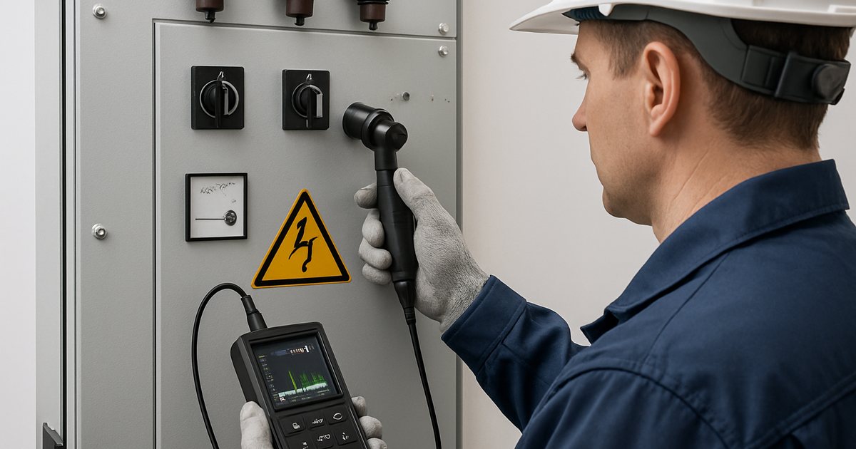
Quick Answer
Partial discharge (PD) is the earliest measurable warning sign of insulation degradation inside medium voltage switchgear, and it can be detected non-invasively with UHF, TEV, HFCT, or ultrasonic sensors — long before it develops into a flashover or an unplanned outage. IEC 60270 defines how PD is measured (in picocoulombs); IEC 62271-203 and customer specifications define the pass/fail limit for a given switchgear type. Retrofitting monitoring onto existing switchgear is possible for most technologies, but specifying sensor provisions at the factory order stage is significantly cheaper and easier than retrofitting later.
Why Partial Discharge Is the Leading Precursor to Switchgear Failure
Utility and industry reliability studies consistently identify insulation-related degradation — of which PD is the measurable early symptom — as one of the largest single categories of medium voltage switchgear failure, commonly cited in the range of roughly a quarter to over a third of all reported failures, alongside mechanical (contact and operating mechanism) faults. The pattern that keeps showing up across these studies is the same: switchgear rarely fails without warning. It fails after a period — sometimes months, sometimes years — during which PD activity was present and measurable, but nobody was measuring it.
This is the core argument for condition monitoring: an unplanned MV switchgear failure does not just cost the price of the damaged panel. It costs the production downtime, the emergency callout, the expedited replacement lead time (often 8–16 weeks for a custom panel), and — in the worst case of an internal arc fault — a safety incident. A monitoring system that flags a developing problem gives you the option to schedule a repair during a planned outage window instead.
What Actually Causes Partial Discharge Inside MV Switchgear
PD is not one single failure mechanism — it is a symptom that shows up through several different physical defects, each with a slightly different signature:
- Voids in cast-resin or solid insulation: Air gaps trapped during the epoxy casting of bushings, current transformers, or solid-insulated RMU modules. Voids have a much lower breakdown strength than the surrounding resin, so PD initiates inside the void well below the rated voltage of the component.
- Floating (loose) metal components: A poorly torqued busbar joint, a loose shield, or a disconnected grounding braid creates a metal part at an indeterminate potential — it discharges to nearby grounded or live metal repeatedly as the voltage cycles.
- Surface tracking and contamination: Dust, moisture, or conductive deposits on an insulator surface create a low-resistance path that produces surface discharge, common in coastal, high-humidity, or heavily industrial environments.
- Corona at sharp edges or points: Air ionizes around a sharp conductor edge or protrusion where the local electric field exceeds the breakdown strength of air — common on poorly finished bus connections or damaged cable terminations.
Each of these produces a different PD signature (magnitude, repetition rate, phase-resolved pattern), which is one reason experienced condition-monitoring programs combine more than one sensor type rather than relying on a single measurement.
IEC 60270 and IEC 62271-203: What the Standards Actually Require
These two standards get confused often because they are frequently cited together, but they answer different questions:
| Standard | What it defines | Applies to | Typical output |
|---|---|---|---|
| IEC 60270 | How to measure partial discharge (test circuit, calibration, apparent charge in pC) | Any insulated electrical equipment — a measurement method, not a product spec | Measured apparent charge (pC) at a specified test voltage |
| IEC 62271-203 | Product requirements for gas-insulated metal-enclosed switchgear (GIS), including PD acceptance using the IEC 60270 method | GIS above 52 kV by scope, widely also applied to MV GIS and gas-insulated RMU modules | Pass/fail against a stated pC limit at 1.1× Ur |
| IEC 62271-200 | Product requirements for metal-enclosed AC switchgear (the base standard covering most MV switchgear and RMUs) | Metal-clad and metal-enclosed switchgear 1–52 kV | PD test is commonly added as an enhanced/optional routine test beyond the base dielectric withstand test, per customer specification |
In practice, many utility specifications and manufacturer routine-test procedures require a measured partial discharge level of ≤10 pC for solid/cast-resin insulated MV switchgear, and some GIS specifications tighten this to ≤5 pC, both measured at 1.1× rated voltage per the IEC 60270 method. These numbers are a routine factory test pass/fail threshold at a single point in time — they are a different thing from online monitoring, which tracks trend over months and years rather than a single pass/fail snapshot. A panel that passed its factory PD test at 8 pC can still develop new PD activity five years later from a loosened connection or contamination; that is exactly the gap online condition monitoring is designed to close.
PD Sensor Technologies Compared: UHF vs TEV vs HFCT vs Ultrasonic
No single sensor technology detects every PD source equally well — this is why the sensor selection question matters more than most buyers expect:
| Sensor type | Detection principle | Frequency range | Best for | Retrofit difficulty |
|---|---|---|---|---|
| UHF (antenna/coupler) | Electromagnetic radiation radiated by the PD event | ~300 MHz – 1.5 GHz | GIS and metal-enclosed switchgear with internal void/floating-potential defects; least sensitive to external electrical noise | Hard — needs a dielectric window or purpose-built sensor port |
| TEV (transient earth voltage) | High-frequency voltage pulse coupled onto the metallic enclosure surface | ~3 MHz – 100 MHz | Metal-clad and metal-enclosed AIS switchgear; good for periodic walk-by surveys | Easy — surface-mounted pad, no compartment access needed |
| HFCT (high-frequency CT clamp) | High-frequency current pulse traveling on the earth strap or cable sheath | ~1 kHz – 20 MHz | Cable terminations and earth connections; good sensitivity, easy installation | Easiest — clamps around an existing earth conductor |
| Airborne ultrasonic | Acoustic emission from the discharge (audible/near-audible range shifted up) | ~20 kHz – 100 kHz | Surface tracking and corona on accessible, non-enclosed surfaces (bushings, open-air joints) | Easy for accessible surfaces; blocked by metal enclosures |
For gas-insulated or fully enclosed metal-clad switchgear, most experienced monitoring programs combine TEV + HFCT for a cost-effective baseline (both retrofit easily) and add UHF only on the highest-criticality bays where the switchgear was specified with sensor provisions from the factory.
Retrofit Monitoring on Existing Switchgear vs Specifying It at Order Time
We get this question constantly from operators of aging switchgear fleets, so it's worth separating clearly:
Retrofitting existing switchgear
- TEV and HFCT sensors can usually be added to any metal-clad/metal-enclosed switchgear regardless of age or original manufacturer, since they mount externally.
- Ultrasonic works on any accessible surface but cannot "see" through a sealed metal enclosure.
- UHF retrofit generally requires either an existing inspection window (rare on older panels) or a planned outage to install a sensor port — this is where retrofit cost and complexity rise sharply.
- Always confirm with the original manufacturer before drilling into a gas-filled (SF6 or solid-insulated) compartment — an improperly sealed retrofit port can compromise the gas system and the enclosure warranty.
Specifying monitoring-ready switchgear at order time
- UHF sensor ports or coupling windows can be built into the compartment design at essentially marginal cost when planned during manufacturing, versus a field retrofit that requires an outage and specialist labor.
- TEV pads can be factory-installed at standard mounting locations, saving the commissioning-stage labor of surveying and drilling.
- Communication wiring (for IEC 61850 or Modbus output) can be routed through the same cable entries used for protection relay wiring, avoiding a second cable-pulling exercise later.
If your fleet replacement or expansion plan spans multiple years, the lowest-total-cost approach is almost always to specify monitoring provisions on new orders now, and use portable TEV/ultrasonic survey instruments as a stopgap on the older fleet until it is replaced. See our full preventive maintenance and testing schedule guide for how PD surveys fit into a broader inspection program.
What to Put in Your RFQ When You Want Monitoring-Ready Switchgear
When we receive an RFQ that specifically asks for condition-monitoring-ready panels, the buyers who get the best-matched proposal (and avoid change orders later) typically include:
- Which bays require monitoring (often only the incoming/transformer bays, not every feeder) — this controls cost significantly since not every panel needs the same sensor density.
- A stated PD acceptance limit in pC at 1.1× Ur, referencing IEC 60270, included as a factory routine test line item — not assumed.
- Preferred communication protocol (IEC 61850 GOOSE/MMS, Modbus TCP, Modbus RTU, or simple dry-contact alarm relay) matched to the existing SCADA/DCS system.
- Whether sensors and acquisition electronics should be quoted included in the base switchgear price or as a separately priced option — this affects how proposals from different manufacturers can be compared apples-to-apples.
- Data retention and access requirements — local HMI display only, or integration with a central asset management platform.
Need help scoping this for a specific project? Contact NAIJI Electric's engineering team — we provide free specification review for monitoring-ready medium voltage switchgear and gas-insulated switchgear orders.
When Does Online PD Monitoring Pay for Itself?
| Scenario | Without monitoring | With monitoring |
|---|---|---|
| Developing insulation defect | Undetected until flashover or trip; often discovered by the outage itself | Trend detected weeks-to-months in advance; repair scheduled during planned downtime |
| Replacement lead time exposure | Emergency order at rush lead time, often 4–8 weeks faster but at a significant cost premium, or extended unplanned downtime waiting for standard lead time | Standard lead time order placed proactively once trend is confirmed |
| Safety risk | Internal arc fault risk if defect progresses undetected to failure | Defect addressed before it reaches a hazardous discharge level |
| Upfront cost | None | Sensor + acquisition cost per monitored bay (see FAQ for typical ranges) |
The economics favor monitoring most clearly on critical, hard-to-quickly-replace bays — main incomers, transformer secondary breakers, and bus-tie breakers where an unplanned outage cascades into a wider loss of supply. It is far less clearly justified on low-criticality, easily spared feeder panels, which is why bay-by-bay scoping (see the RFQ checklist above) matters more than "monitor everything."
NAIJI Electric's Approach to Monitoring-Ready Switchgear
Our ASN3i-12 intelligent medium voltage switchgear line is built with sensor mounting provisions and IEC 61850 communication as standard design features rather than a field afterthought, and our engineering team can add TEV pad mounting points, HFCT-ready earth strap routing, or a UHF sensor port to any of our metal-clad or gas-insulated MV switchgear and GIS lineups at the design stage — before the panels are built, not after they're installed. For projects with an existing switchgear fleet, our engineering team can also advise on which retrofit sensor type fits your specific enclosure design and whether a proposed retrofit affects your existing warranty.
Related guides: Ring Main Unit (RMU) Guide | IEC 62271 Standard Guide | Metal-Clad Switchgear Testing Standards | Switchgear kA Rating Calculation Guide