Last Updated: 2026-10-12
A medium voltage switchgear commissioning checklist must cover 28+ discrete tests before the equipment can be safely energized. The critical pass/fail values: insulation resistance above 1,000 MOhm at 1 kV test voltage, power frequency withstand at 28 kV for 1 minute (12 kV class) or 50 kV for 1 minute (24 kV class), vacuum circuit breaker opening time under 40 ms, closing time under 80 ms, and main contact resistance below 200 micro-ohms. Missing any one of these tests risks catastrophic failure during energization — including internal arc faults that generate temperatures exceeding 35,000 degrees F and blast pressures above 2,000 lbs/ft2.
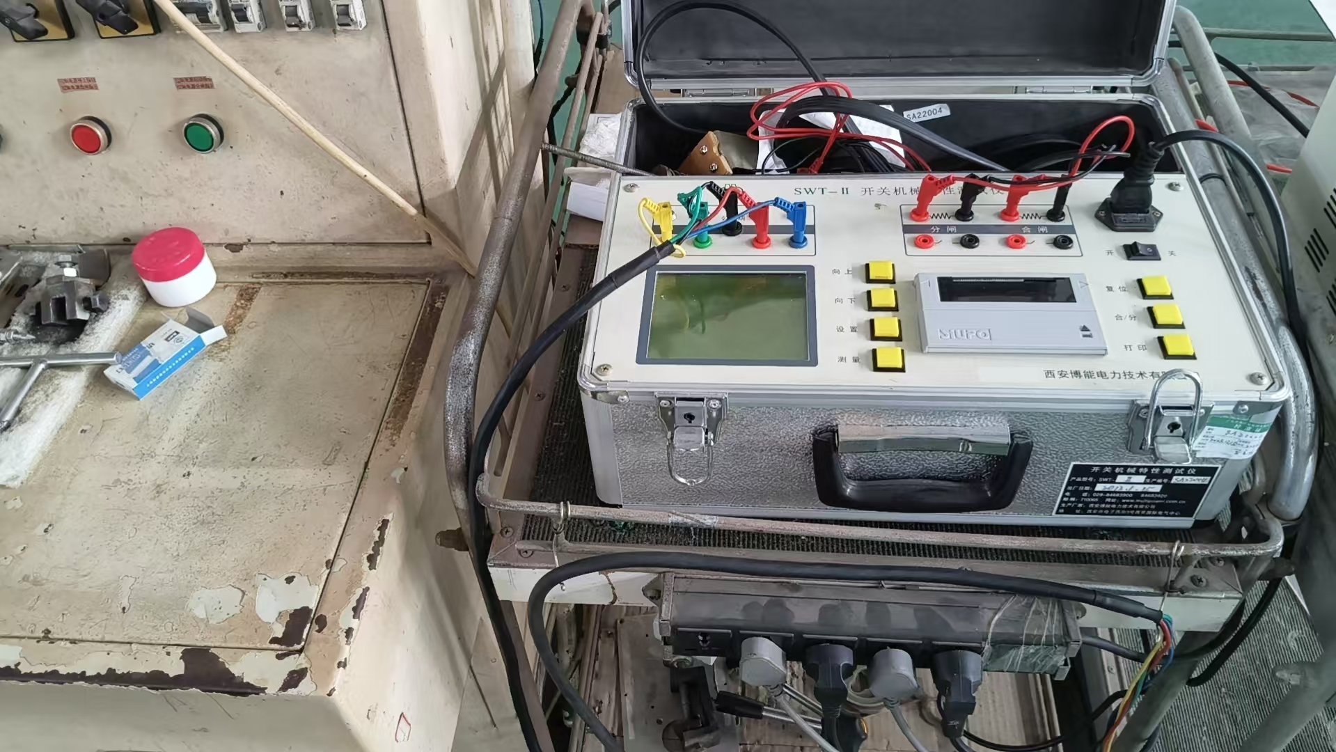
This guide provides the complete pre-energization commissioning checklist based on IEC 62271-200, IEC 62271-100, and IEEE C37.09 requirements. As a manufacturer of medium voltage switchgear and vacuum circuit breakers, we write from direct experience commissioning 12 kV to 40.5 kV equipment across utility substations, industrial plants, and data center facilities worldwide.
Commissioning vs Factory Acceptance Testing: What Changes On-Site?
Many engineers confuse commissioning with factory acceptance testing (FAT). While both involve similar test procedures, the objectives differ fundamentally:
| Aspect | Factory Acceptance Test (FAT) | Site Commissioning |
|---|---|---|
| Location | Manufacturer's factory | Project installation site |
| Purpose | Verify design and manufacturing quality | Verify equipment survived transport and is correctly installed |
| Test voltage level | 100% of rated withstand voltage | 75-80% of rated withstand voltage (typical) |
| Reference standard | IEC 62271-200 Clause 7 / IEEE C37.20.2 Section 5 | IEC 62271-200 Clause 8 / Project specification |
| Who performs | Manufacturer's test team | Commissioning engineer (independent or manufacturer's) |
| Acceptance criteria | Absolute values per standard | Comparison against FAT baseline + absolute minimums |
The key principle: site commissioning tests are comparative. You compare every measured value against the FAT baseline. A 15% degradation in insulation resistance from FAT values — even if the absolute value still passes — triggers investigation because it indicates something changed during shipping or installation.
Phase 1: Visual Inspection & Mechanical Checks (Day 1)
Before connecting any test instruments, a systematic visual and mechanical inspection catches the majority of transport-related damage. This phase takes 4-6 hours for a 10-panel lineup.
1.1 Shipping Damage Assessment
- External enclosure: Check all panels for dents, scratches, paint damage, or deformation. Measure door gaps — uneven gaps indicate frame distortion during transit.
- Shock indicators: If tilt or impact indicators were attached during shipping, photograph their status before disturbing them. A tripped impact indicator means the equipment experienced forces exceeding the rated shipping shock limit (typically 3-5g) and requires enhanced internal inspection.
- Foundation bolts: Verify all anchor bolts are torqued to specification. Typical values: M16 bolts at 190 Nm, M20 bolts at 380 Nm.
- Bus bar connections: Inspect all inter-panel bus bar joints. Bolted connections must be torqued to manufacturer specifications (typically 40-60 Nm for M12 bus bar bolts, verified with a calibrated torque wrench).
1.2 Mechanical Interlock Verification
Mechanical interlocks prevent dangerous operating sequences. Every interlock must be functionally tested before electrical testing begins:
- Breaker racking interlock: Verify the breaker cannot be racked into the connected position while the breaker is closed. Attempt to rack in with breaker closed — it must be physically blocked.
- Earthing switch interlock: Confirm the earthing switch cannot be closed while the breaker is in the connected position, and the breaker cannot be racked in while the earthing switch is closed.
- Door interlock: Verify compartment doors cannot be opened while the associated circuit is live (breaker connected, earthing switch open).
- Key interlocks: Test all Kirk-key or Castell-type key exchange sequences. Document that the correct key sequence is required — no key should be removable out of sequence.
1.3 Circuit Breaker Mechanical Operation
Each vacuum circuit breaker must be mechanically operated before electrical testing to verify the spring charging motor, trip mechanism, and counter are functioning correctly:
- Charge closing springs manually and electrically (verify spring charge motor completes in under 15 seconds for stored-energy mechanisms)
- Perform 5 close-open operations with the breaker in the test/disconnected position
- Verify the mechanical operations counter advances correctly
- Check slow-closing mechanism function if equipped
- Confirm anti-pumping relay prevents multiple close operations on a held-close command
Phase 2: Electrical Testing (Days 2-3)
Electrical testing forms the core of switchgear commissioning. These tests require calibrated instruments and must be performed by qualified personnel following strict safety procedures per arc flash safety requirements.
2.1 Insulation Resistance Testing
Insulation resistance (IR) testing is the first electrical test because it determines whether the equipment is safe for high-voltage testing. A failed IR test means moisture or contamination is present — applying the withstand test voltage would cause a flashover.
| Equipment Voltage Class | Megohmmeter Test Voltage | Minimum Acceptable IR | Target IR (New Equipment) |
|---|---|---|---|
| 12 kV | 2.5 kV or 5 kV | >1,000 MOhm | >5,000 MOhm |
| 24 kV | 5 kV | >1,000 MOhm | >5,000 MOhm |
| 36 kV | 5 kV or 10 kV | >1,000 MOhm | >10,000 MOhm |
| 40.5 kV | 10 kV | >1,000 MOhm | >10,000 MOhm |
Test procedure per IEC 62271-200:
- Disconnect all secondary wiring, surge arresters, and voltage transformers from the bus
- Measure phase A to ground, phase B to ground, phase C to ground
- Measure phase A to B, phase B to C, phase A to C
- Record the 1-minute value (IR at 60 seconds of applied voltage)
- Calculate the Polarization Index (PI) = IR at 10 minutes / IR at 1 minute. A PI above 2.0 indicates clean, dry insulation. PI below 1.5 warrants investigation.
- Apply temperature correction if ambient temperature differs from 20 degrees C (IR approximately halves for each 10 degrees C increase)
Common IR failure causes: Moisture absorption during ocean shipping (especially for equipment stored in unheated containers for 4-6 weeks), condensation from temperature cycling during storage, contamination from construction dust in the switchroom, or insulator surface tracking from micro-cracks sustained during transport.
2.2 Power Frequency Withstand Test (Hi-Pot)
The power frequency withstand test verifies that the switchgear insulation can handle the rated overvoltage conditions specified in IEC 62271-200 and ANSI C37.20.2. This is the most critical dielectric test during commissioning.
| Voltage Class | IEC Type Test Withstand | Site Commissioning (80%) | ANSI C37.20.2 Type Test | Duration |
|---|---|---|---|---|
| 12 kV | 28 kV rms | 22.4 kV rms | 36 kV rms | 1 minute |
| 24 kV | 50 kV rms | 40 kV rms | 60 kV rms | 1 minute |
| 36 kV | 70 kV rms | 56 kV rms | 80 kV rms | 1 minute |
| 40.5 kV | 85 kV rms | 68 kV rms | 95 kV rms | 1 minute |
Important: Site commissioning test voltage is typically 75-80% of the factory type test voltage. This lower value accounts for the fact that equipment has been subjected to factory testing already and prevents unnecessary insulation stress. However, some project specifications require full type test voltage at site — always verify the applicable specification before testing.
Test connections: Apply the test voltage phase-to-ground with the other two phases grounded, then rotate through all three phases. Leakage current must remain below the test equipment's threshold (typically less than 5 mA for a clean pass). Any flashover, sustained arcing, or excessive leakage current is an immediate failure.
2.3 Circuit Breaker Timing Tests
Circuit breaker timing tests verify that the vacuum circuit breaker operates within the time tolerances specified in IEC 62271-100 and IEEE C37.09. Out-of-tolerance timing can result in asynchronous pole closing (causing motor and transformer inrush damage), failure to clear faults within the protection coordination time, or re-strike due to late contact separation.
| Parameter | IEC 62271-100 Requirement | Typical VCB Values | IEEE C37.09 Requirement |
|---|---|---|---|
| Opening time (O) | Per manufacturer's declaration | 25-40 ms | Per manufacturer's declaration |
| Closing time (C) | Per manufacturer's declaration | 50-80 ms | Per manufacturer's declaration |
| Close-open time (CO) | Per manufacturer's declaration | 50-80 ms from close command to contacts open | Per manufacturer's declaration |
| Pole synchronism (closing) | Less than 3 ms between first and last pole | 1-2 ms | Less than 3 ms (5 ms some specs) |
| Pole synchronism (opening) | Less than 3 ms between first and last pole | 1-2 ms | Less than 3 ms |
| Contact travel (stroke) | Per manufacturer's design | 8-12 mm for 12 kV VCB | Per manufacturer's design |
| Contact velocity (opening) | Per manufacturer's declaration | 0.9-1.3 m/s | Per manufacturer's declaration |
Test procedure: Use a circuit breaker analyzer (e.g., Megger TM1800, Omicron CPC 100) to simultaneously capture all three poles. Perform minimum 3 close operations and 3 open operations at rated control voltage, then repeat at 85% and 110% of rated control voltage. IEC 62271-100 requires the breaker to operate correctly across the control voltage range of 85% to 110% of rated. Record contact travel curves if available — changes in travel curve shape from the FAT baseline indicate mechanism wear or misadjustment.
Critical tolerance: If opening time exceeds 40 ms, the breaker may not clear faults within the protection coordination time assumed by the relay settings. If pole synchronism exceeds 3 ms, transient recovery voltage (TRV) distribution across poles becomes uneven, increasing re-strike risk at current zero. Both conditions require mechanism adjustment before energization.
2.4 Contact Resistance Measurement
Contact resistance testing uses a micro-ohmmeter (typically injecting 100-200 A DC) to measure the resistance across each closed main contact, bus bar joint, and cable termination. High contact resistance causes localized heating, leading to thermal runaway and eventual failure.
| Connection Type | Maximum Acceptable Resistance | Test Current |
|---|---|---|
| VCB main contacts (per pole) | <200 micro-ohms (new) | 100-200 A DC |
| Bus bar bolted joint | <20 micro-ohms per joint | 100-200 A DC |
| Isolating contacts (draw-out) | <100 micro-ohms | 100 A DC |
| Earthing switch contacts | <200 micro-ohms | 100 A DC |
| Cable termination | <50 micro-ohms | 100 A DC |
Compare results against the manufacturer FAT report. An increase of more than 50% from the FAT value — even if the absolute value is within limits — indicates oxidation, contamination, or loosening of the contact system during transport.
2.5 Earthing System Verification
The switchgear earthing system must be verified before any high-voltage testing is performed. This includes:
- Main earth bar continuity: Measure resistance from each panel earth terminal to the main earth bar — must be less than 0.5 ohm
- Earth bar to station ground grid: Verify the connection resistance is less than 1 ohm (typically much lower, ideally under 0.1 ohm)
- CT/PT secondary grounding: Verify all CT and PT secondary circuits are grounded at one point only to prevent circulating ground currents
- Surge arrester grounding: Confirm surge arrester ground connections are as short and direct as possible, with no loops
- Door bonding straps: Verify all doors and removable panels have earthing braids connected
Phase 3: Protection & Control Testing (Days 3-4)
3.1 CT and PT Verification
Current transformer (CT) and potential transformer (PT) verification includes:
- CT ratio check: Primary inject 100% rated current and verify secondary output matches the nameplate ratio (tolerance: less than 1% for metering CTs, less than 3% for protection CTs)
- CT polarity test: Using a DC battery flick test or dedicated polarity tester, confirm P1-S1 polarity markings are correct. Wrong polarity causes directional protection maloperation and differential relay false tripping
- CT insulation resistance: Measure secondary to ground at 500 V — must exceed 100 MOhm
- PT ratio and polarity: Apply rated primary voltage and verify secondary output voltage and polarity
- CT winding resistance: Measure using a Kelvin bridge — compare against factory values for winding integrity verification
3.2 Protection Relay Testing
Every protection relay function specified in the protection coordination study must be verified by secondary injection testing. This is typically performed by a specialist relay engineer:
- Overcurrent elements (50/51): Inject multiples of pickup current and verify trip time matches the specified curve (IEC, IEEE, or inverse definite minimum time). Typical tolerance: less than 5% of declared operating time at 3x pickup.
- Earth fault elements (50N/51N): Verify pickup sensitivity (typically 10-20% of CT rated current for sensitive earth fault on resistance-grounded systems)
- Differential elements (87): Inject balanced current through the protected zone and verify stability, then inject unbalanced current to verify correct tripping at the set differential current threshold
- Under/over voltage (27/59): Verify pickup and dropout voltages and time delays
- Breaker failure (50BF): Simulate a breaker failure condition and verify the backup trip is issued to upstream breakers within the set time (typically 150-250 ms)
3.3 SCADA and Communication Check
For remotely operated switchgear, verify:
- All digital inputs (breaker status, earthing switch status, alarms) correctly map to SCADA points
- All digital outputs (remote close/trip, earthing switch operation) function correctly from the SCADA master station
- Analog values (currents, voltages, power) display correctly with correct scaling factors
- Communication protocol (IEC 61850, DNP3, Modbus) is functional with correct addressing and polling intervals
- Failsafe behavior: verify what happens when communication is lost — the switchgear must default to a safe state (typically "last command hold" or "trip on communication loss" depending on the application)
Phase 4: Pre-Energization Final Checks & Energization Procedure
4.1 Pre-Energization Checklist
Before applying primary voltage, the commissioning engineer must verify every item on this final checklist:
- All test equipment has been disconnected and removed from the switchgear
- All temporary grounds and test leads have been removed
- All bus bar compartment doors are closed and latched
- All CT secondary circuits are either connected to their relay/meter loads or short-circuited (NEVER left open-circuited — an open CT secondary generates dangerous voltages up to several kV)
- All surge arresters are connected
- All earthing switches are in the OPEN position
- All circuit breakers are in the OPEN and DISCONNECTED position
- Space heaters are energized (anti-condensation heaters must run continuously)
- Ventilation system is functional
- Fire detection and suppression systems in the switchroom are functional
- All commissioning test reports have been reviewed and signed
- An energization permit has been issued by the responsible authority
4.2 First Energization Sequence
The energization procedure must be performed by qualified personnel with appropriate PPE per the arc flash hazard analysis (see our arc flash protection guide for PPE category determination):
- Energize the incoming bus (no load): Close the incoming breaker/switch from the upstream source. Monitor the bus voltage — it should stabilize at nominal within 2 seconds with no voltage dips or oscillations.
- Soak period: Leave the bus energized with no load for 1-4 hours. During this period, monitor for partial discharge sounds (crackling, buzzing), abnormal temperature rise on bus bar joints (use IR thermography if accessible through IR windows), and any unusual odor indicating insulation breakdown.
- Energize feeders one at a time: Close each feeder breaker individually with its downstream load disconnected, then connect the load. This sequential approach isolates any faulted feeder without tripping the entire bus.
- Load monitoring: After all feeders are energized, monitor phase currents, voltages, and power factor for the first 24 hours. Confirm load distribution matches the design single-line diagram expectations.
12 Common Commissioning Failures and Root Causes
Based on our experience commissioning hundreds of switchgear panels from 12 kV to 40.5 kV, these are the most frequently encountered commissioning problems:
| # | Failure Mode | Root Cause | Solution |
|---|---|---|---|
| 1 | Low insulation resistance (<100 MOhm) | Moisture absorption during ocean shipping (4-6 weeks in container) | Run space heaters for 24-48 hours in enclosed switchroom, retest. If IR does not recover, inspect for cracked insulators. |
| 2 | VCB opening time exceeds 40 ms | Trip spring not fully charged or mechanism damper out of adjustment after transport | Verify spring charge indicator, re-adjust mechanism per manufacturer procedure, retest. |
| 3 | Pole synchronism exceeds 3 ms | Uneven linkage adjustment or one pole mechanism binding | Inspect linkage pins and bearings, lubricate per manufacturer spec, re-adjust individual pole linkages. |
| 4 | Bus bar joint contact resistance >50 micro-ohms | Bolts loosened during shipping vibration | Disassemble joint, clean surfaces with abrasive pad, apply contact grease, retorque to specification. |
| 5 | Breaker truck will not rack into connected position | Floor unevenness or rail misalignment (>2 mm tolerance) | Shim switchgear base, realign rails using manufacturer guide rails and feeler gauges. |
| 6 | CT polarity reversed | Incorrect wiring at terminal block (swapped S1/S2) | Repeat polarity test, correct wiring per drawing, reverify with injection test. |
| 7 | Protection relay trips at wrong current | CT ratio mismatch between relay settings and installed CT | Verify installed CT ratio matches relay settings and protection coordination study. Common error: 600/5 CT installed but relay set for 800/5. |
| 8 | Earthing switch interlock does not engage | Alignment pin out of position after panel leveling | Re-adjust interlock pin position with breaker in each position (connected/test/disconnected). |
| 9 | Hi-pot test failure at 80% voltage | Cable termination not properly stress-relieved or contamination on bushing surface | Inspect cable terminations for correct stress cone installation, clean bushing surfaces with isopropanol, retest. |
| 10 | Space heater circuit not functional | Heater auxiliary supply breaker tripped or wiring disconnected for shipping | Restore auxiliary power, verify heater thermostat operation (should cycle on below 40-50% RH). |
| 11 | SCADA points show wrong breaker status | Digital input wiring swapped between panels at marshalling cabinet | Verify point-to-point wiring against SCADA I/O list, correct at marshalling terminal. |
| 12 | Partial discharge detected during soak period | Foreign object left in bus compartment or loose hardware | De-energize immediately, open bus compartment, perform thorough internal inspection. Common objects: loose bolts, wire ties, tools left during installation. |
Required Test Equipment for MV Switchgear Commissioning
A complete commissioning requires the following calibrated instruments:
- Megohmmeter (insulation tester): 5 kV or 10 kV rated, with PI (Polarization Index) capability — e.g., Megger MIT1025, Fluke 1555
- AC hi-pot test set: Adjustable 0-100 kV output, with leakage current measurement — capacity matched to the equipment voltage class
- Circuit breaker analyzer: 3-pole simultaneous timing, travel measurement, coil current analysis — e.g., Megger TM1800, Omicron CPC 100
- Micro-ohmmeter: 100-200 A DC injection, 1 micro-ohm resolution — e.g., Megger DLRO200
- CT analyzer: Ratio, polarity, burden, and excitation curve testing — e.g., Omicron CT Analyzer
- Protection relay test set: 3-phase current and voltage injection — e.g., Omicron CMC 356, Megger SMRT46
- Power quality analyzer: For 24-hour post-energization monitoring — e.g., Fluke 1760
- Infrared camera: For thermal monitoring of bus joints and cable terminations — minimum 320x240 resolution
Commissioning Documentation Requirements
A compliant commissioning report must include:
- Equipment identification (manufacturer serial numbers, voltage rating, current rating for each panel)
- All test results with pass/fail status, compared against FAT baseline values
- Calibration certificates for all test instruments used
- Photographs of nameplate data, test setups, and any anomalies found
- Record of all mechanical interlock tests with pass/fail results
- Protection relay settings as-commissioned (printed from relay configuration software)
- Single-line diagram marked up with as-built changes (if any)
- Punch list of outstanding items with responsible party and completion date
- Energization authorization signed by the project engineer and site safety officer
This documentation package becomes the permanent maintenance baseline for the switchgear installation. All future maintenance and testing results will be compared against these commissioning values to detect insulation degradation, contact wear, and mechanism deterioration over the equipment's 30+ year service life.
NAIJI Electric Commissioning Support
NAIJI Electric provides factory-dispatched commissioning engineers for all switchgear orders above 10 panels. Our commissioning service includes complete FAT baseline data packages, calibrated test equipment, and detailed commissioning reports per IEC 62271-200 Clause 8 requirements. For smaller installations, we provide remote commissioning guidance with video support and standardized test procedure documents.
Every switchgear shipment from our factory includes the complete FAT report, recommended commissioning test procedure, and spare parts kit. This ensures your on-site commissioning team has the baseline data needed for comparative testing — reducing commissioning time by 20-30% compared to equipment shipped without FAT documentation.
Need commissioning support or a pre-energization test procedure for your switchgear project? Contact our engineering team with your project voltage class, panel count, and installation schedule. We provide commissioning planning, on-site support, and complete documentation packages for utilities, industrial plants, data centers, and renewable energy substations worldwide.