Last Updated: 2026-10-13 · Written by the NAIJI Electric engineering team. We build low-voltage switchgear and medium-voltage protection equipment; the outgoing-circuit schedule of an LV panel is where we see trip-curve mistakes most often.
Key Takeaways
- B, C and D change only the instantaneous trip band: 3-5x, 5-10x and 10-20x rated current (IEC 60898-1). The overload behaviour (1.13x / 1.45x In) is identical.
- Each step up the alphabet halves the maximum earth fault loop impedance. On a 2.5/1.5 mm² circuit with Ze = 0.35 Ω, a B20 allows about 78 m of cable, a C20 about 32 m and a D20 about 8 m.
- LED lighting is limited by driver inrush, not watts: one common 150 W driver allows 4 units on a B16 but 7 on a C16, so a "lighting = Type B" rule can leave a breaker running at 16% of its rating.
- "Type B circuit breaker" can also mean a Type B RCD (DC-sensitive earth leakage, IEC 62423). It is a different device with a different job.
Quick Answer: Which MCB Curve Do You Need?
Use Type B for resistive and general circuits with long cable runs, Type C for motors, pumps, fluorescent and LED lighting groups and most commercial loads, and Type D only for high-inrush loads such as LV transformers and welders on short, low-impedance circuits. Pick the least sensitive curve the load needs to start, then check that the circuit still delivers enough fault current to trip that curve instantly.
That second check is the one most guides skip. A curve that stops nuisance tripping can also stop the breaker from clearing an earth fault in 0.4 s. The rest of this guide gives you the numbers for both sides of the decision.
What B, C and D Actually Mean (IEC 60898-1 Test Points)
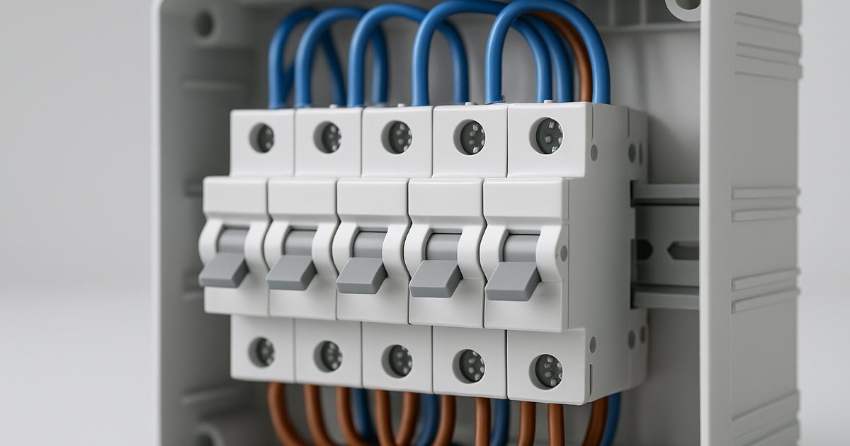
Every MCB has two trip elements. The thermal element (a bimetal strip) handles slow overloads. The magnetic element (a solenoid) trips instantly on large currents. The letter only describes where the magnetic element takes over.
IEC 60898-1 defines the curve by five test points. You can check any datasheet against this table:
| Test | Current | Required result | Same for B / C / D? |
|---|---|---|---|
| a | 1.13 × In (from cold) | No trip for 1 h | Yes |
| b | 1.45 × In (right after test a) | Trip within 1 h | Yes |
| c | 2.55 × In (from cold) | Trip between 1 s and 60 s (In ≤ 32 A) or 1-120 s (In > 32 A) | Yes |
| d | B: 3 × In · C: 5 × In · D: 10 × In | No trip in 0.1 s | No |
| e | B: 5 × In · C: 10 × In · D: 20 × In | Trip in under 0.1 s | No |
Two practical consequences follow. First, a C16 does not carry more continuous current than a B16. Both protect the same cable against overload, so changing the curve never lets you skip cable sizing (see our circuit breaker sizing guide). Second, the band between test d and test e is a tolerance. A B16 may trip anywhere from 48 A to 80 A, and you must design for both ends: the load inrush must stay below 48 A, and the fault current must exceed 80 A.
Some manufacturers also sell K (typically about 8-14 × In) and Z (about 2-3 × In) characteristics. These are manufacturer-defined devices under IEC 60947-2, not IEC 60898-1 curves, so read the specific datasheet. The difference between the two standards is covered in IEC 60898 vs IEC 60947.
Matching the Curve to the Load: Inrush by Load Type
The question to ask is not "what kind of building is this" but "what is the first 10 ms of this load's current". Typical inrush ranges:
| Load | Typical inrush (multiple of running current) | Duration | Usual curve |
|---|---|---|---|
| Heaters, socket circuits, resistive loads | ~1× | - | B |
| Incandescent / halogen lamps | 10-15× (cold filament) | A few ms | B or C |
| LED drivers, switch-mode power supplies | Capacitor charging: tens of amps per driver | Under 1 ms | C for groups; check driver datasheet |
| Small DOL motors, pumps, compressors | 6-8× FLC, higher first-half-cycle peak | 0.1-several s | C |
| LV control and isolation transformers | 10-15× or more on energization | ~10-100 ms | D |
| Welding sets, X-ray, UPS bypass | Very high, manufacturer-specific | Varies | D (or K) |
For motors, the curve must also coordinate with the overload relay or motor protection circuit breaker downstream. For loads above 63 A, or where you need adjustable settings, you are in MCCB territory; see MCB vs MCCB.

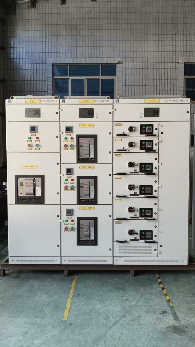
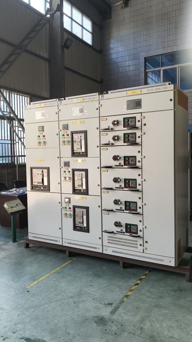
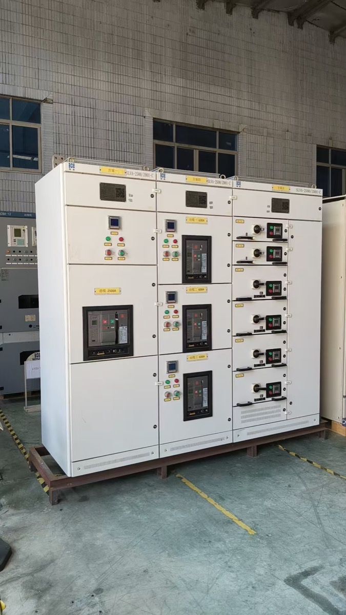
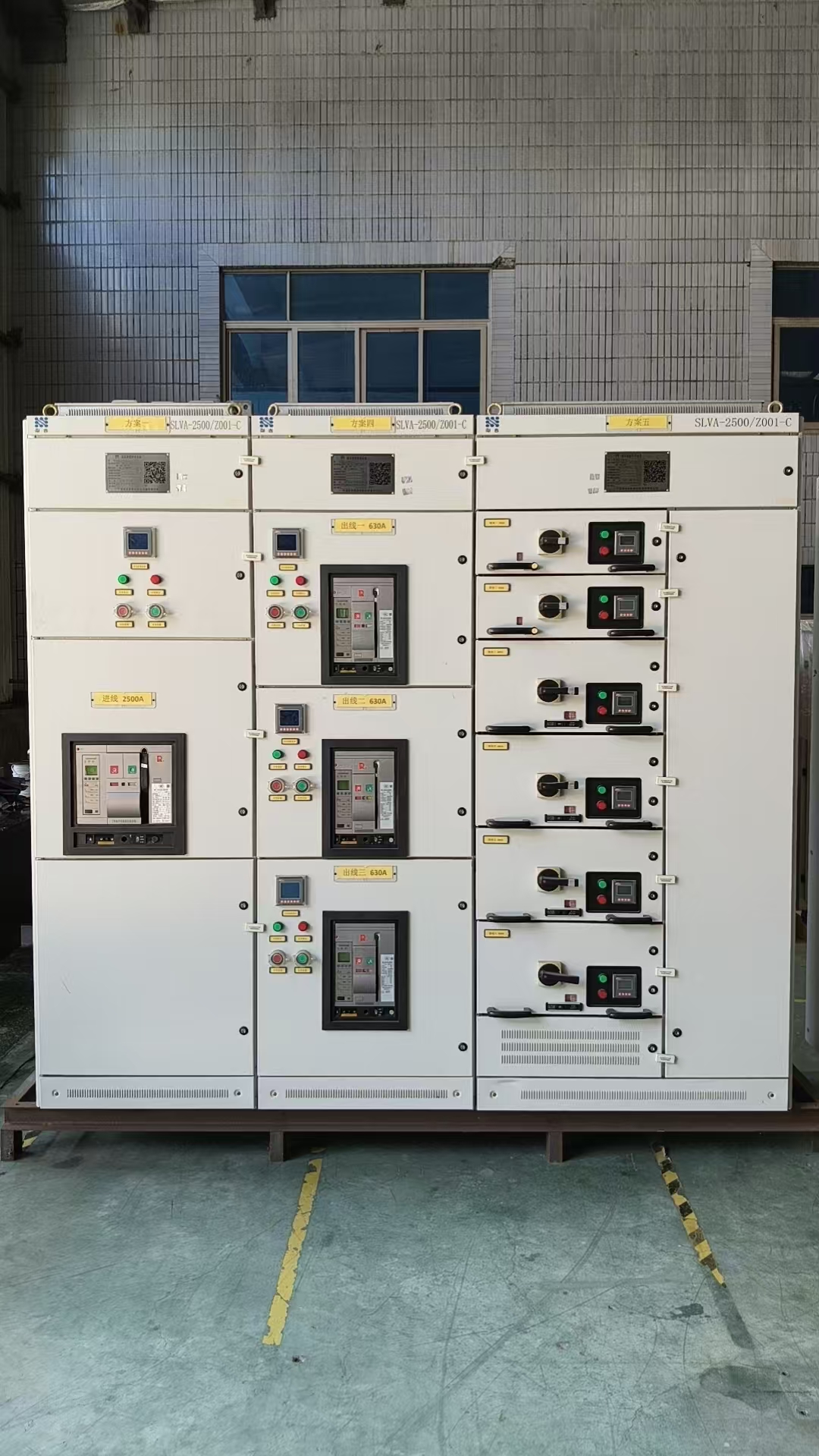
Specifying a low-voltage panel? Send us the outgoing-circuit schedule (load type, rating, cable length, earthing system) and we will check the curve and breaking capacity for each way before quoting. Request a panel review or see our low-voltage switchgear range.
The Hidden Cost of a Higher Curve: Loop Impedance and Cable Length
In a TN system, a final circuit up to 32 A at 230 V must disconnect an earth fault within 0.4 s (IEC 60364-4-41). An MCB only does that if the fault current reaches its instantaneous threshold (test point e). That sets a maximum earth fault loop impedance, Zs:
Zs(max) = 0.95 × 230 V ÷ (5, 10 or 20 × In)
The 0.95 is the minimum voltage factor. These results reproduce the B and C figures in BS 7671 Table 41.3 exactly:
| Rating | Type B max Zs (Ω) | Type C max Zs (Ω) | Type D max Zs (Ω) |
|---|---|---|---|
| 6 A | 7.28 | 3.64 | 1.82 |
| 10 A | 4.37 | 2.19 | 1.09 |
| 16 A | 2.73 | 1.37 | 0.68 |
| 20 A | 2.19 | 1.09 | 0.55 |
| 32 A | 1.37 | 0.68 | 0.34 |
Now turn impedance into cable length. Zs = Ze + (R1 + R2) × L, where Ze is the external loop impedance and R1 + R2 is the line-plus-protective-conductor resistance. We used 19.51 mΩ/m for 2.5/1.5 mm² copper and 10.49 mΩ/m for 6/2.5 mm² (values at 20 °C), multiplied by 1.2 for conductor operating temperature, and Ze = 0.35 Ω, a common TN-C-S design value:
| Circuit | Type B | Type C | Type D |
|---|---|---|---|
| 16 A, 2.5/1.5 mm² | ~102 m | ~43 m | ~14 m |
| 20 A, 2.5/1.5 mm² | ~78 m | ~32 m | ~8 m |
| 32 A, 6/2.5 mm² | ~81 m | ~26 m | Not achievable (0.34 Ω < Ze 0.35 Ω) |
Read the last cell carefully. A D32 cannot meet 0.4 s on a 0.35 Ω supply at any cable length; the supply impedance alone uses up the whole budget. This is why "just fit a D curve" is the wrong fix for nuisance tripping. If a long circuit really needs a C or D curve, the usual options are a larger protective conductor, a shorter run, or an RCD to provide fault protection (permitted by IEC 60364-4-41 where Zs cannot be met). On TN-S supplies with Ze = 0.8 Ω, every length in this table gets shorter again. Our switchgear earthing guide explains how the earthing system sets Ze.
LED Lighting: Why "Lighting = Type B" Fails
LED drivers are switch-mode power supplies. At switch-on their input capacitors charge in a spike of tens of amps lasting a fraction of a millisecond. One driver is harmless; twenty on the same breaker, switched together, add up.
Driver makers publish the limit directly. The Mean Well HLG-150H datasheet lists a cold-start inrush of 65 A (425 µs at 50% Ipeak, 230 VAC) and allows a maximum of 4 units on a 16 A Type B breaker or 7 units on a 16 A Type C. Four 150 W drivers draw roughly 600 W, about 2.6 A at 230 V. The B16 is full at about 16% of its thermal rating because of inrush, not load.
| 16 A breaker | Max HLG-150H drivers | Approx. steady load | % of 16 A used |
|---|---|---|---|
| Type B | 4 | ~600 W / 2.6 A | ~16% |
| Type C | 7 | ~1,050 W / 4.6 A | ~29% |
Three ways to put more drivers on a circuit: change to a C curve (after the loop impedance check above), split the group across more ways, or fit an inrush current limiter. Always use the figure from the actual driver datasheet. Limits vary widely between models and are not interchangeable.
"Type B Circuit Breaker": MCB Curve or RCD Type?
Many searches for "type b circuit breaker" are really about residual-current devices. The letters mean different things on the two devices:
| Type B MCB | Type B RCD / RCBO | |
|---|---|---|
| What the letter describes | Magnetic trip band: 3-5 × In | Residual-current waveforms detected |
| Standard | IEC 60898-1 | IEC 62423 (with IEC 61008/61009) |
| Protects against | Overload and short circuit | Earth leakage, including smooth DC |
| Typical use | Lighting, sockets, long resistive circuits | EV chargers, three-phase VFDs, PV inverters, medical equipment |
| Relative price | Low (same band as C/D) | Several times a Type A RCD |
The RCD hierarchy runs AC → A → F → B. Each type detects everything the previous one does, plus more. A Type A RCD can be "blinded" by more than about 6 mA of smooth DC leakage, which is why EV charging installations call for either a Type B RCD or a Type A RCD plus a 6 mA DC detection device. An RCBO combines both functions, so it carries two letters: for example a C16 Type A RCBO has a C trip curve and Type A residual sensing. When you write an RFQ, spell out both. See MCB, MCCB, RCCB and RCBO compared for the full device family.
IEC vs North America: Where B/C/D Does Not Apply
More than a third of this site's search impressions come from the United States, so this point matters. UL 489 branch-circuit breakers do not use B, C or D letters. Their instantaneous pickup is shown on the manufacturer's time-current curve, and motor branch circuits are sized under NEC 430.52 rules instead.
The DIN-rail devices sold in North America with B/C/D curves are usually UL 1077 supplementary protectors. They protect equipment inside a machine or panel, but they cannot be used as branch-circuit protection. If you are exporting an IEC panel to the US, or buying "MCBs" for a US job, check which listing the device has. The same IEC/North American split runs through medium-voltage equipment too; see ANSI vs IEC switchgear standards.
Selection Checklist: Five Questions Before You Pick a Curve
- What is the load's inrush, from the datasheet? Motors: locked-rotor current. Drivers: the "max units per breaker" row. Transformers: energization multiple.
- What is the lowest curve that rides through it? The inrush peak must stay below the bottom of the band (3, 5 or 10 × In).
- Does the circuit meet max Zs for that curve? Measure or calculate Ze + (R1 + R2) × L and compare with the table above. If not, shorten the run, upsize the CPC, or add an RCD.
- Is the breaking capacity enough? Icn (6 kA or 10 kA under IEC 60898-1) must exceed the prospective short-circuit current at the board. Near a large transformer, 10 kA or an MCCB is often needed. Our short-circuit rating guide shows the calculation.
- Does it discriminate with the upstream device? A D-curve outgoing way under a small upstream MCB will often trip both. Check selectivity tables from the manufacturer.

Sourcing Notes: Price, Stock and What to Put in the RFQ
Changing the curve rarely changes the price. In most catalogs a B16, C16 and D16 in the same frame and breaking capacity sit in the same price band. Our MCB vs MCCB comparison puts MCBs at roughly USD 3-25 per pole depending on brand, breaking capacity and certification. The real difference is availability: B and C curves are stocked by every distributor, while D curves, 50/63 A ratings and 10 kA versions often have lead times.
For an OEM or panel order, an MCB line item should state: standard (IEC 60898-1 or IEC 60947-2), curve, rated current, poles, Icn/Icu, rated voltage, frequency, terminal type and required certificates (CB, CE, or UL listing). If you are comparing factories, our list of top MCB manufacturers in China covers MOQs and certifications.
Related guides: Miniature Circuit Breaker (MCB) Guide | How to Size a Circuit Breaker | IEC 60898 vs IEC 60947 | MCB vs MCCB
Request a quote for low-voltage switchgear with a checked circuit schedule. Send your single-line diagram, earthing system and outgoing-circuit list to NAIJI Electric. We will return curve, rating and breaking-capacity recommendations for each way with the quotation.
Zs values are calculated from Zs = 0.95 × U0 ÷ Ia with U0 = 230 V and match BS 7671 Table 41.3 for Type B and C devices; always verify against the edition of the wiring rules that applies to your project. Cable lengths are design estimates for radial circuits and exclude voltage drop, which may be the tighter limit. LED driver figures are from the Mean Well HLG-150H specification (rev. 2026-07-24).